MyMoto
MyMoto is an onging project.
The OG Motocompo

1983 Honda Motocompo, yellow.
Spotted on Facebook Marketplace, Seattle’s SoDo Moto imported 7 of these cute little trunk scooters. Since COVID, nearly everything has become collectable for those with disposable income. A new one of these scooters in good cosmetic and functional condition will run you ~$7000.
As much as I’d love one of these little vintage scooters, that’s a bit out of my budget.
Looks like I’ll have to make one myself.
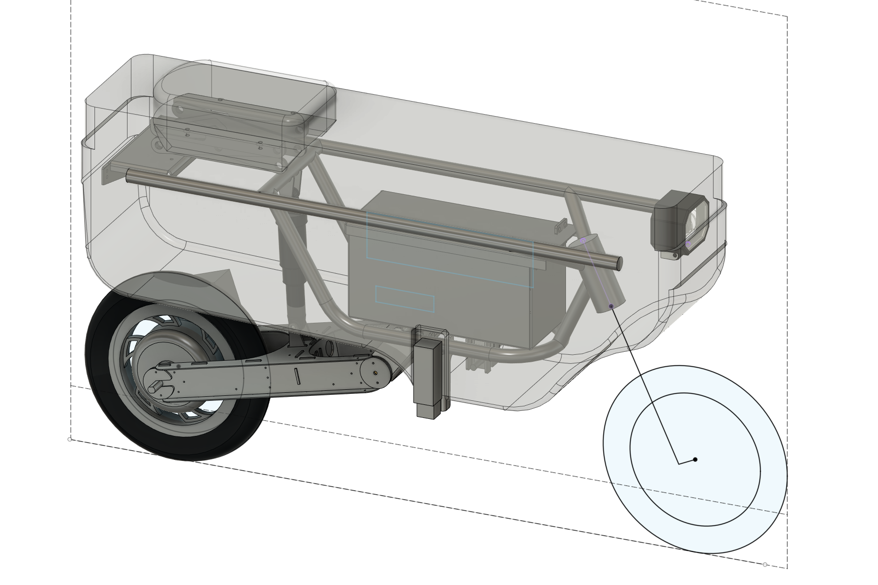
Using modern day components something like this can be had in electric that will not only be faster but also lighter, and more powerful. Of course, this will likely not carry the same charm as the original. So this one will be MyMoto.
Having found images of the frame through a 2018 Japanese listing on yahoo auctions, the frame looked simple enough. I asked SoDo Moto if I could see one in person and take some measurements to get started.
Now, to break each component down into sub projects.
The Frame
From some measurements, I was able to deduce the general package size. Reaching out to minibike enthusiasts about frame material, it seems that 4130 DOM (drawn over mandrel) 7/8” Round Tube with 0.065” to 0.083” wall thickness was the way to go. To make sure that this project was freezable, countless hours were put into hunting down purchasable components to remove as much design work as possible. I’ve settled on 12” wheels with a hub-motor and a 48V battery system.
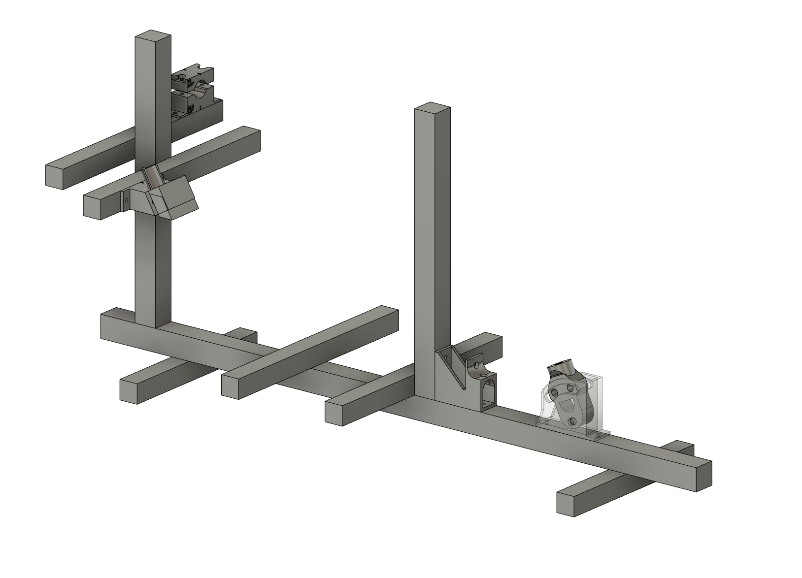
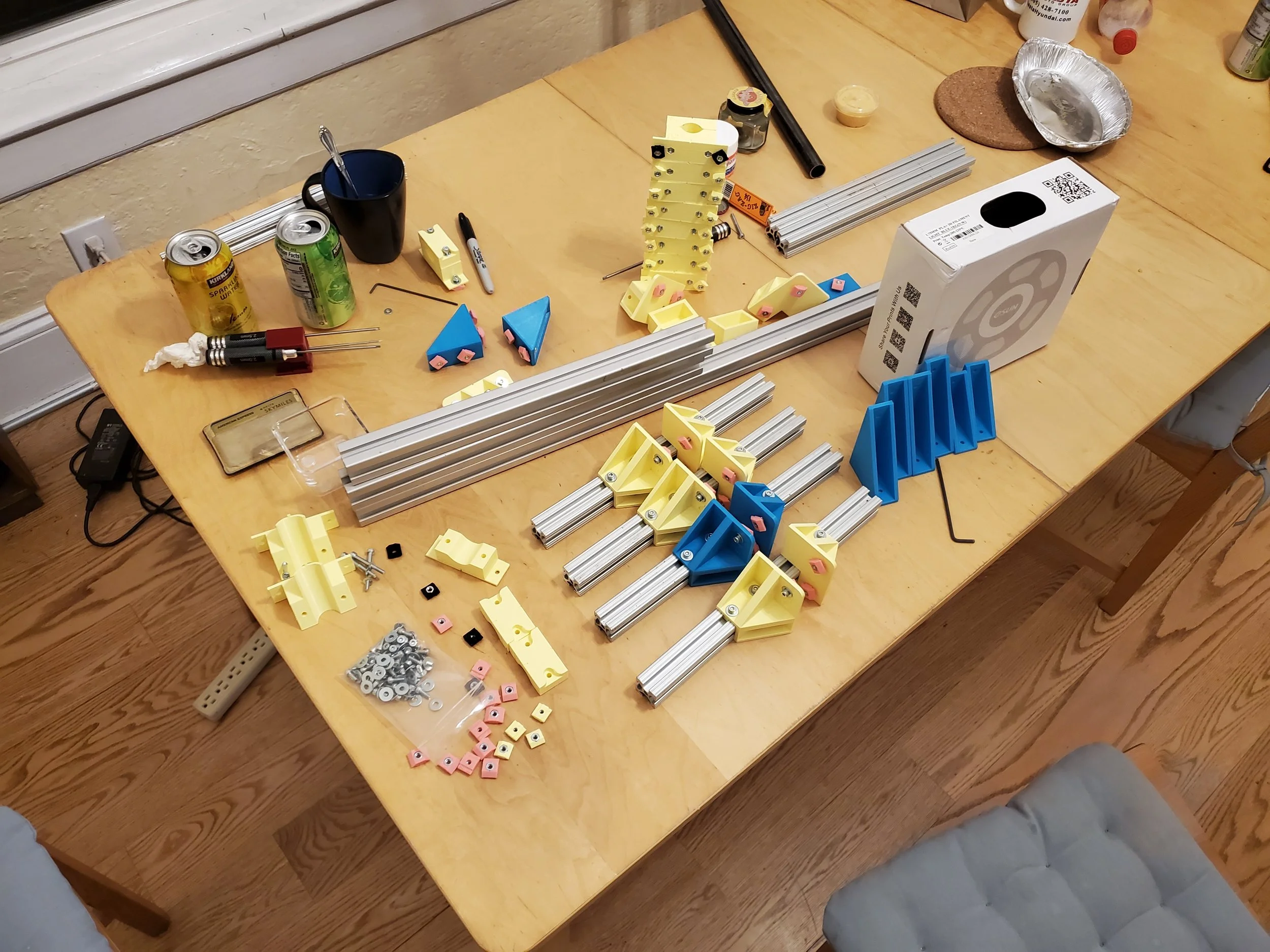
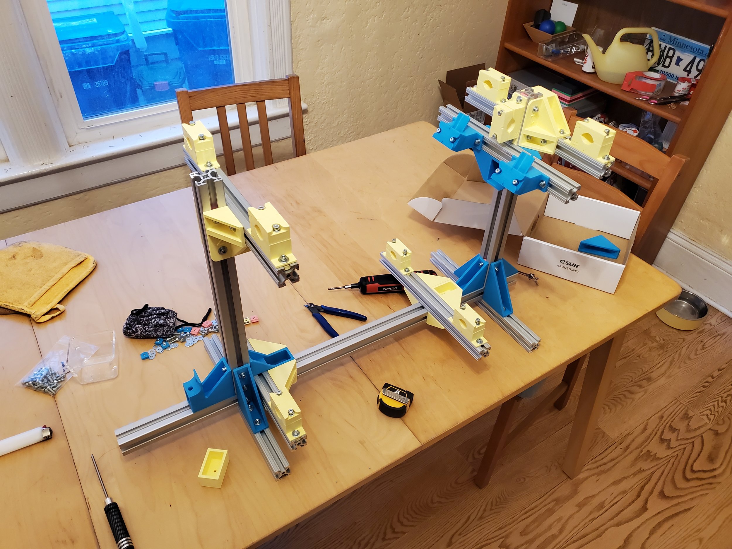
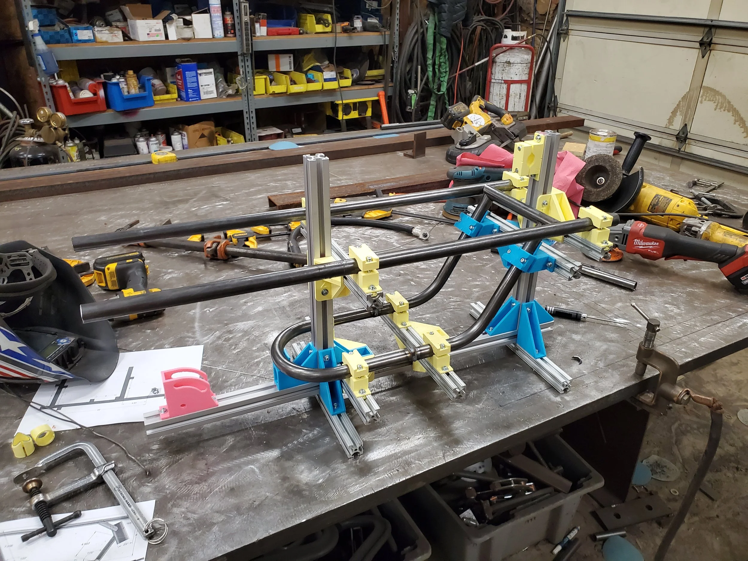
The first thing I learned from this project: making a jig is much more work than constructing the frame.
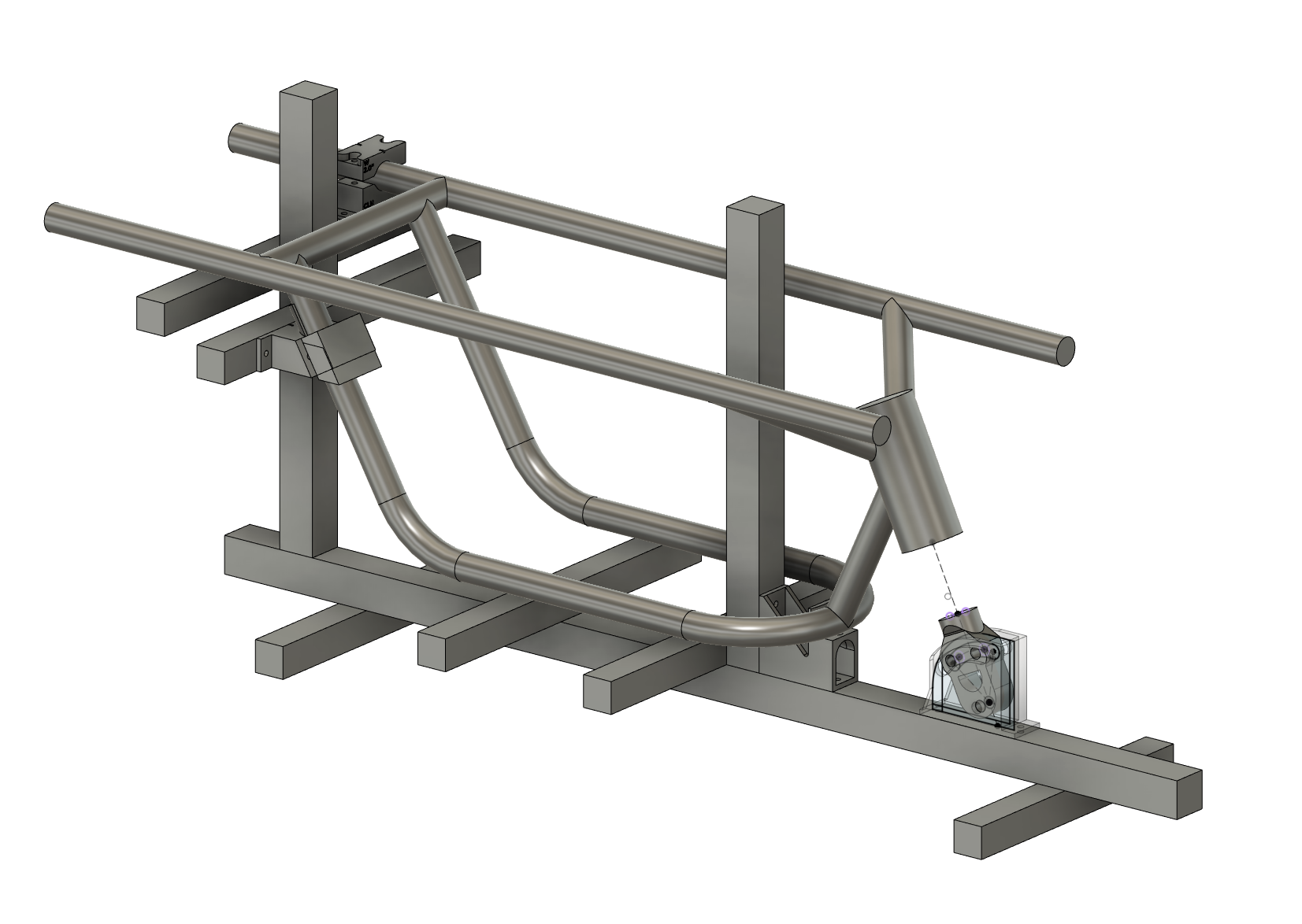
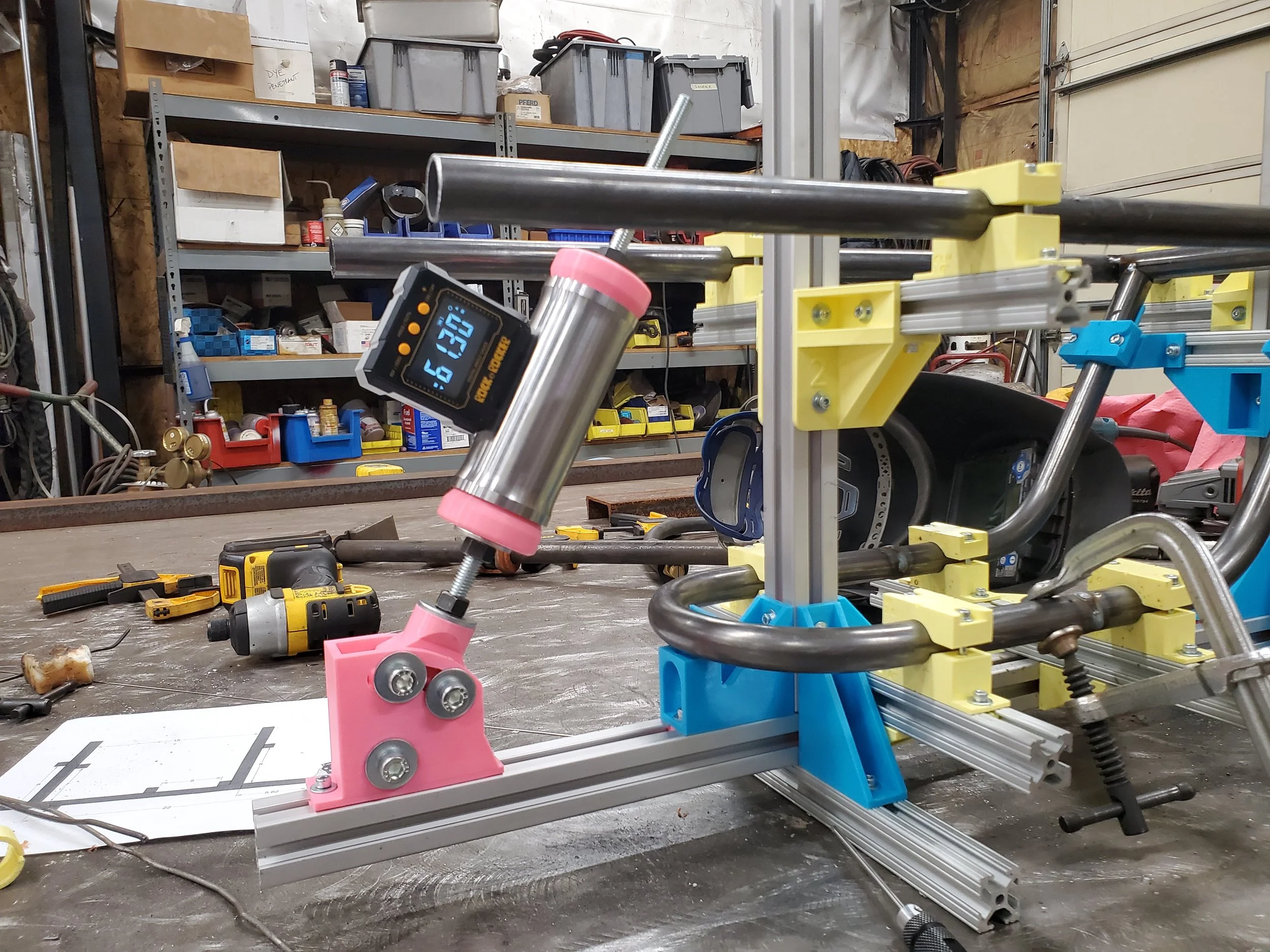
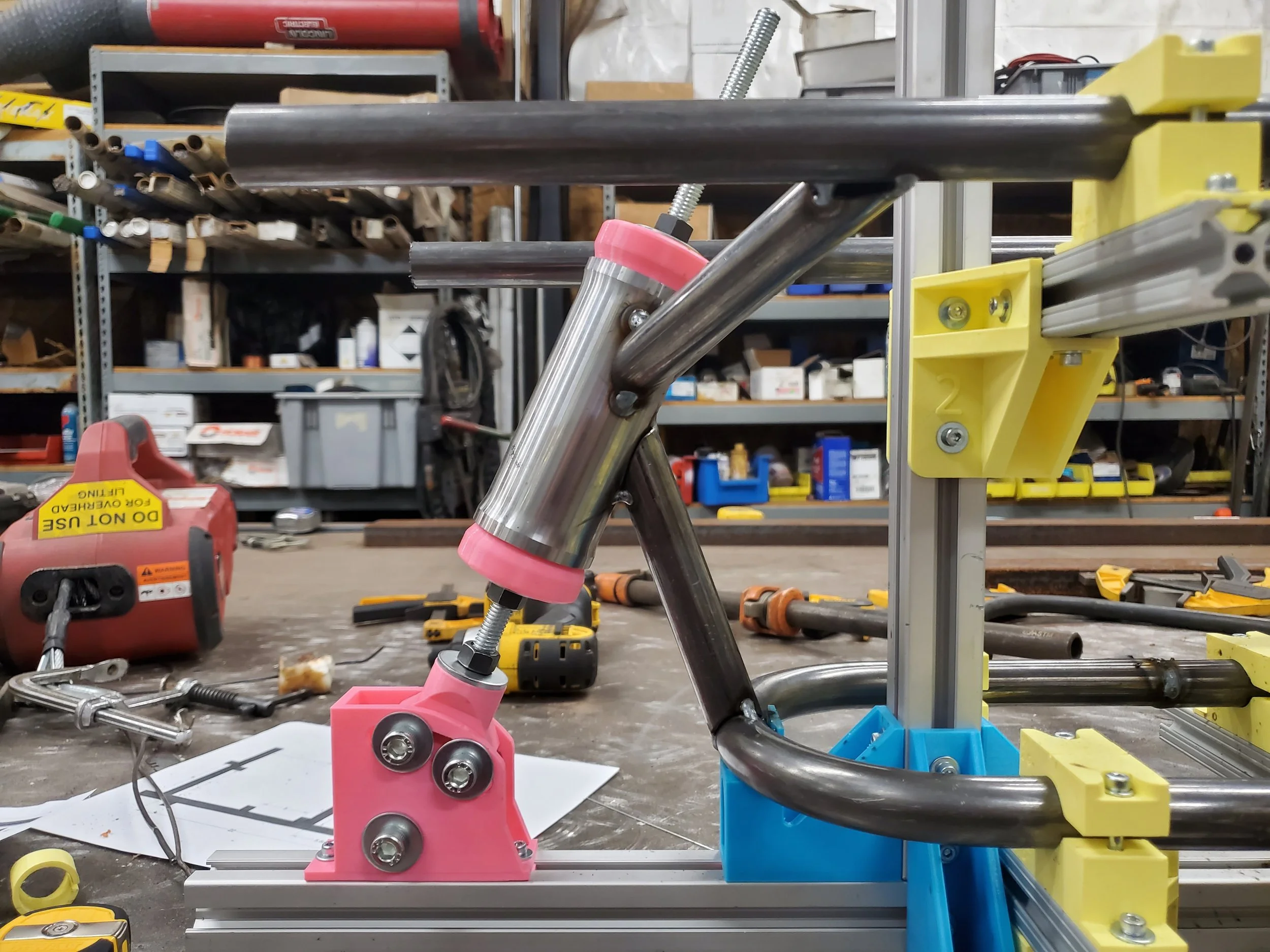
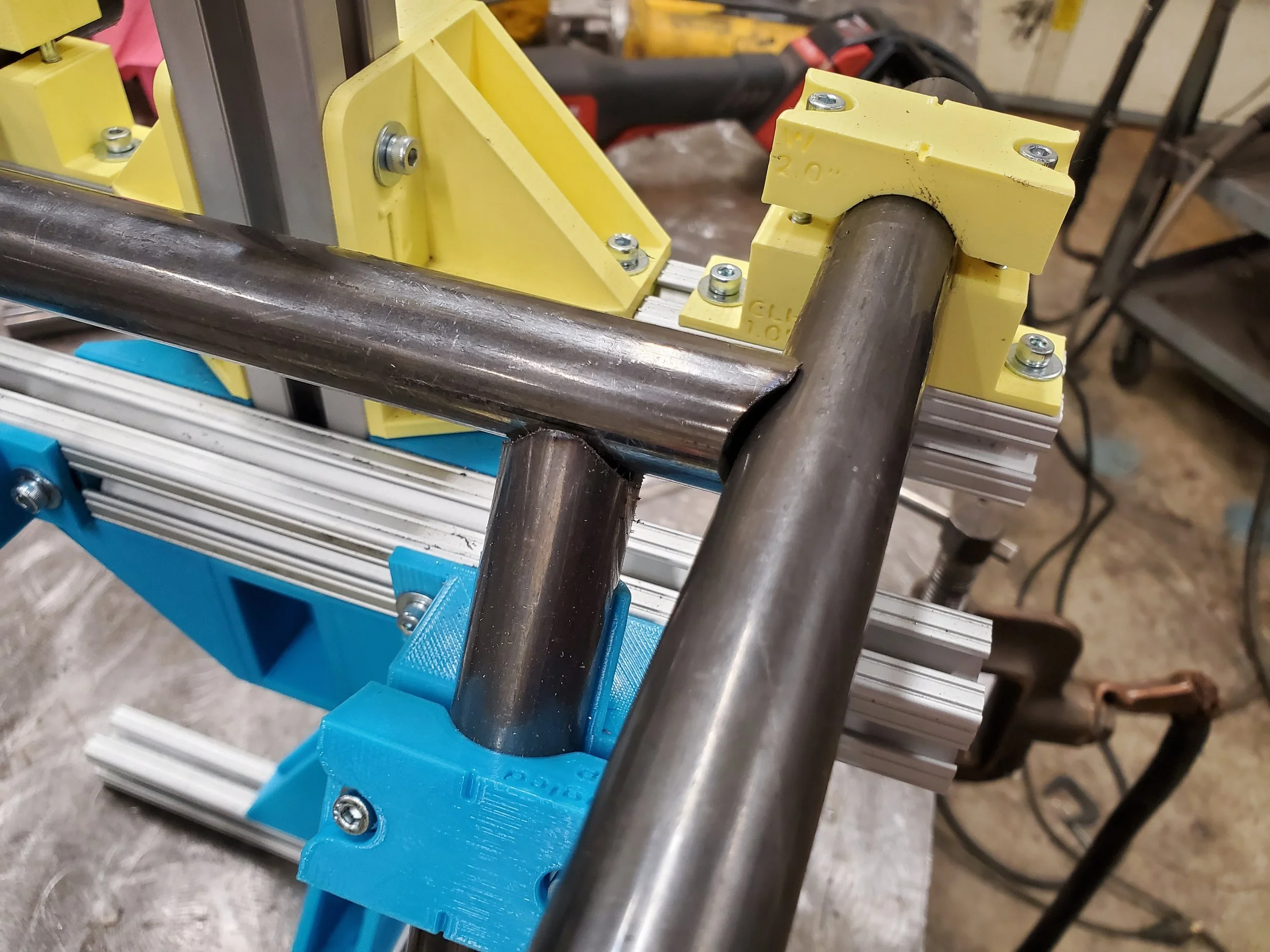
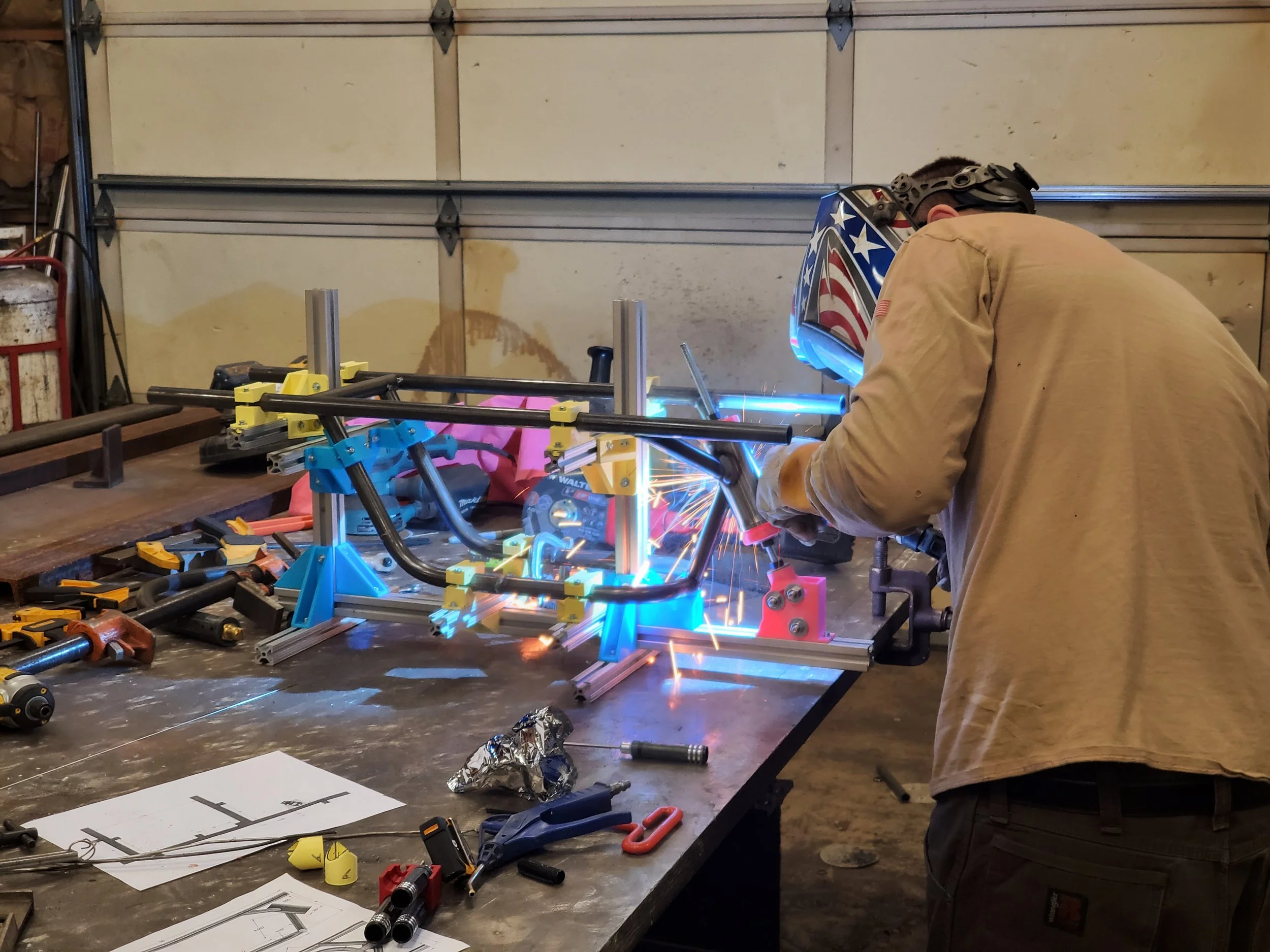
The jig was planned using scrap 80/20, slotted aluminum extrusion and PLA 3D printed brackets were used for clamping the pipes in place. I think next time I would just buy brackets, it was not worth the print time.
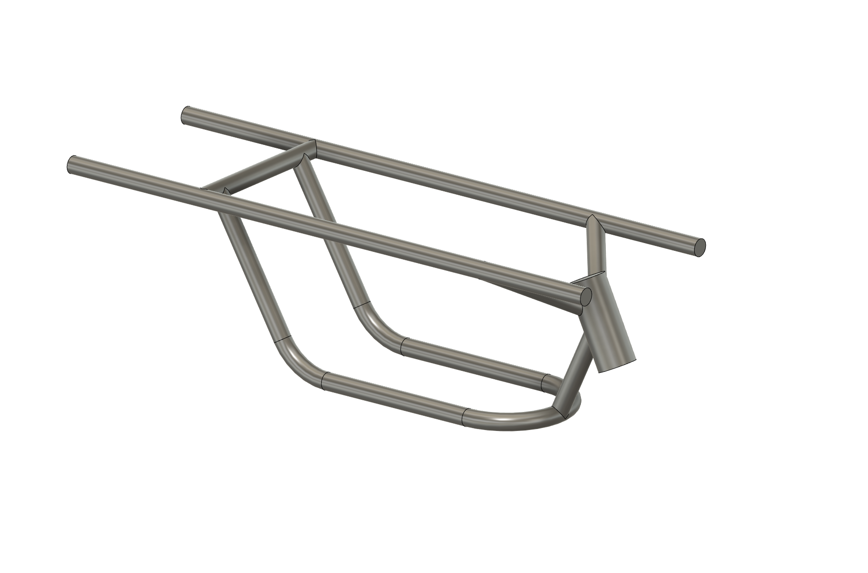
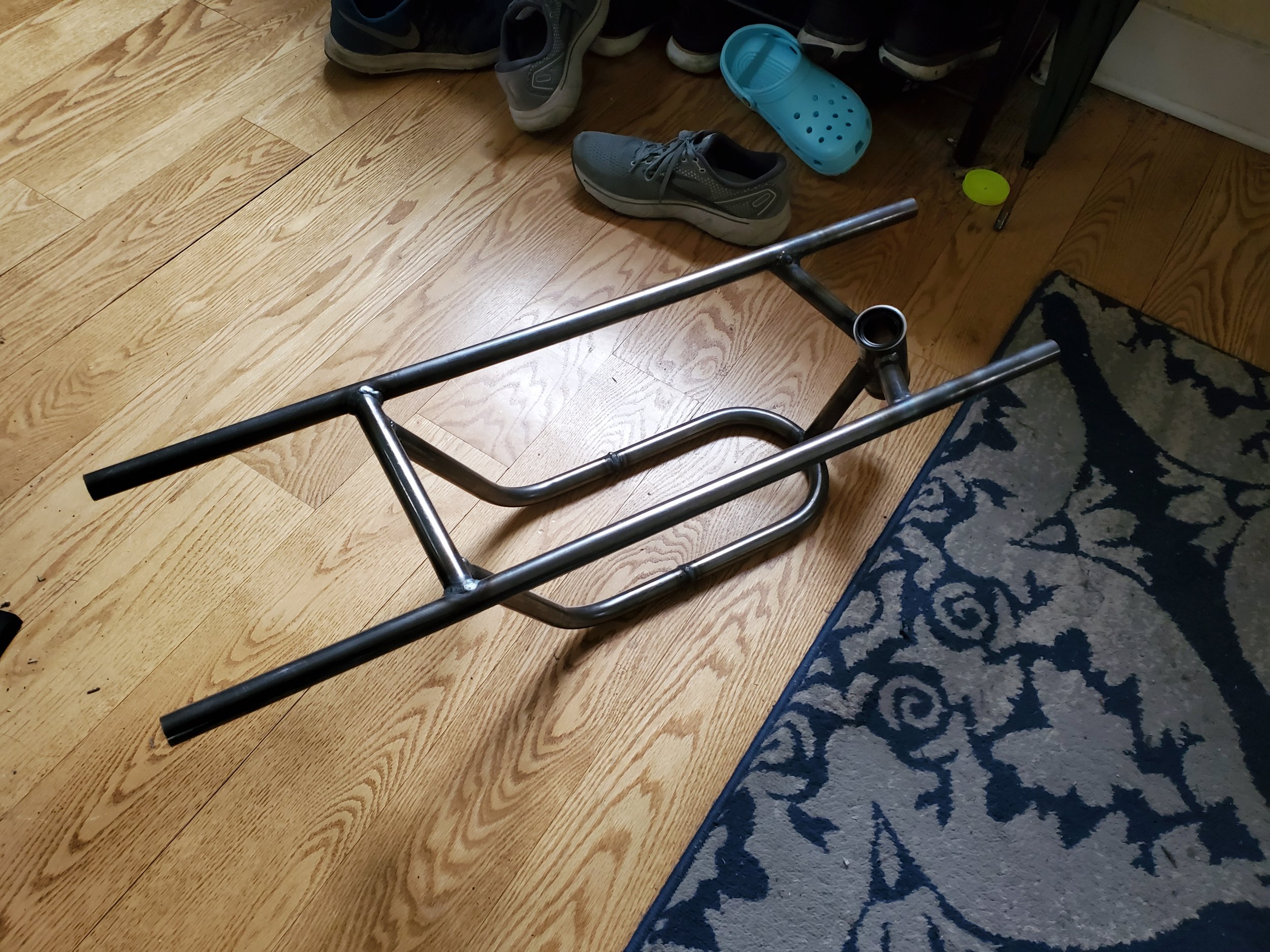
Through the help of a local welder, I was able to get some pipes bent and butt-welded into a basic frame.

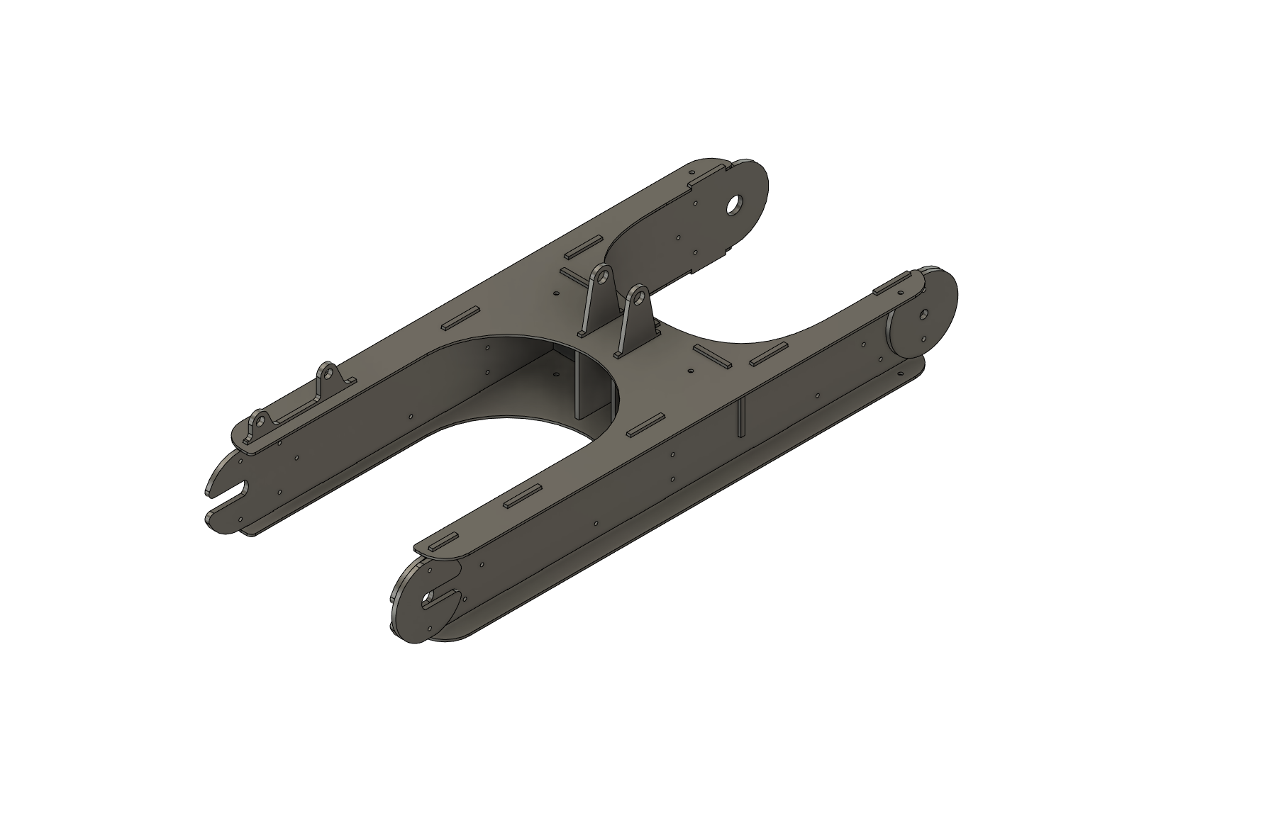
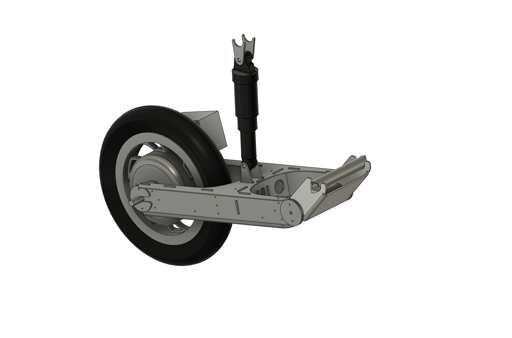
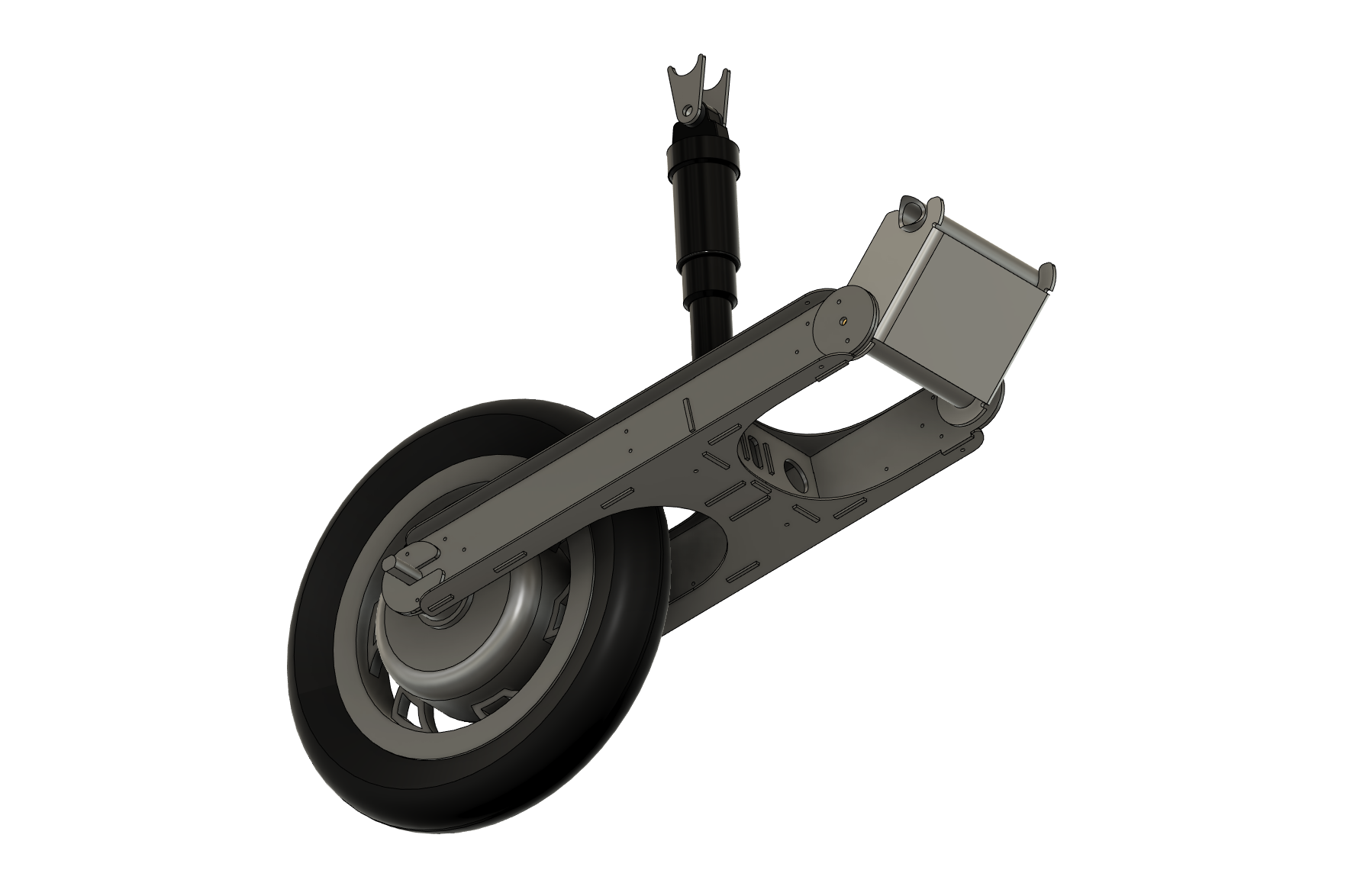
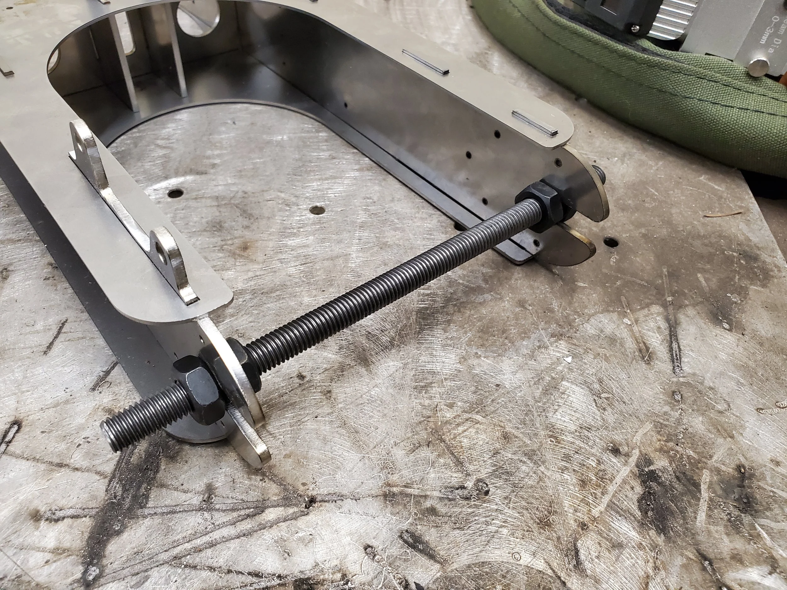
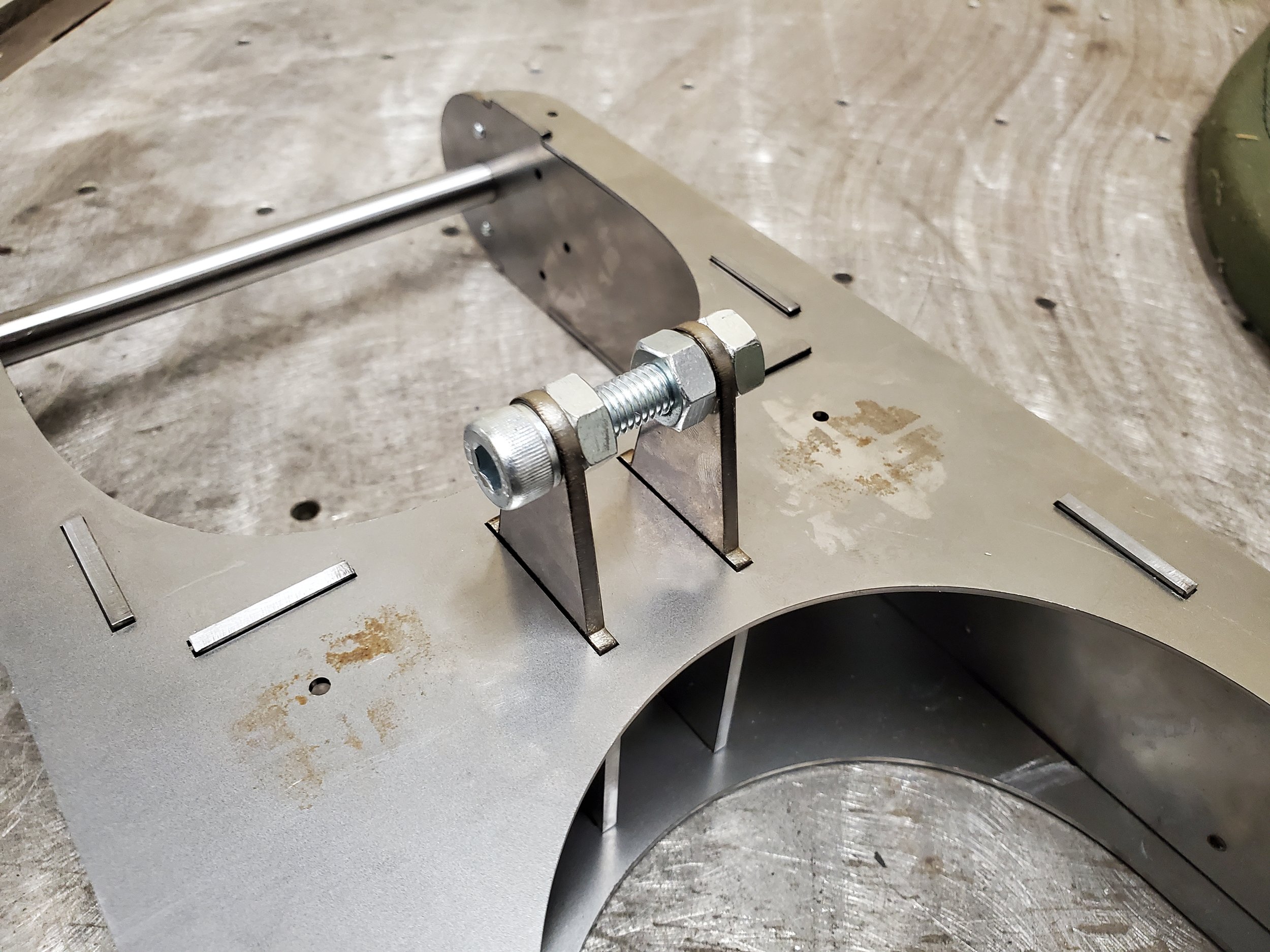
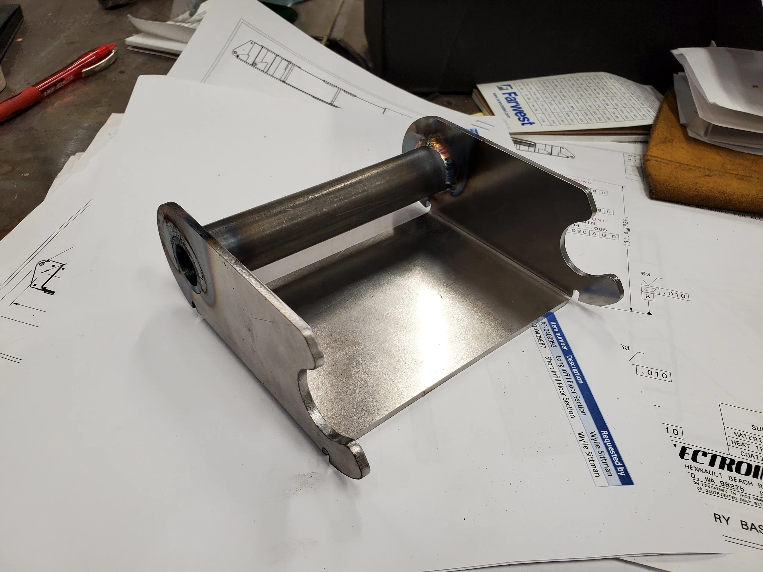
The Swingarm
Next up was the swingarm. This included how it attached to the scooter as well as how it interreacts with the suspension. The suspension was designed around a typical mountain bike air shock/strut. This is so that it will be infinitely adjustable to rider weight and won’t require trial and error of spring weights.
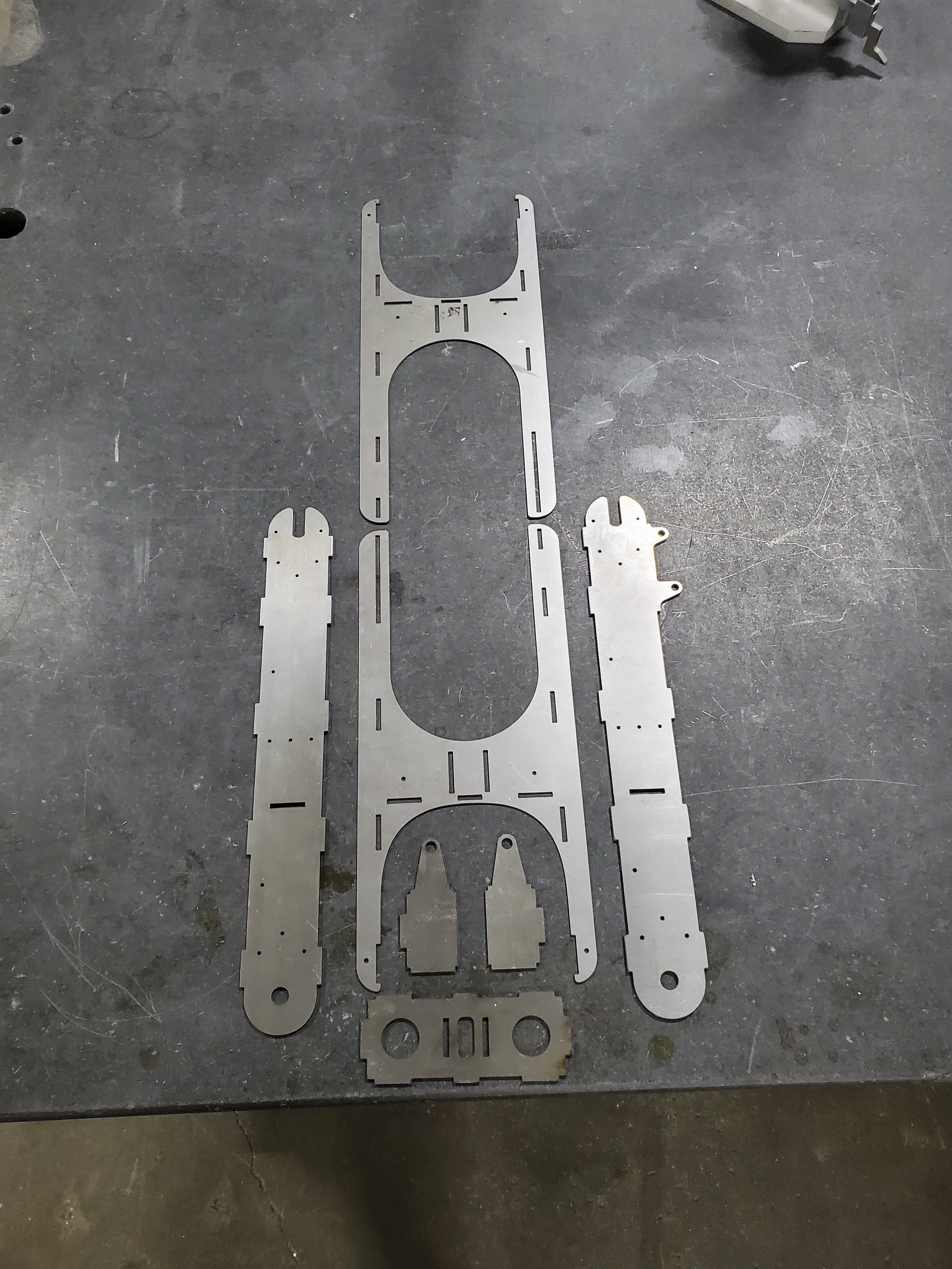
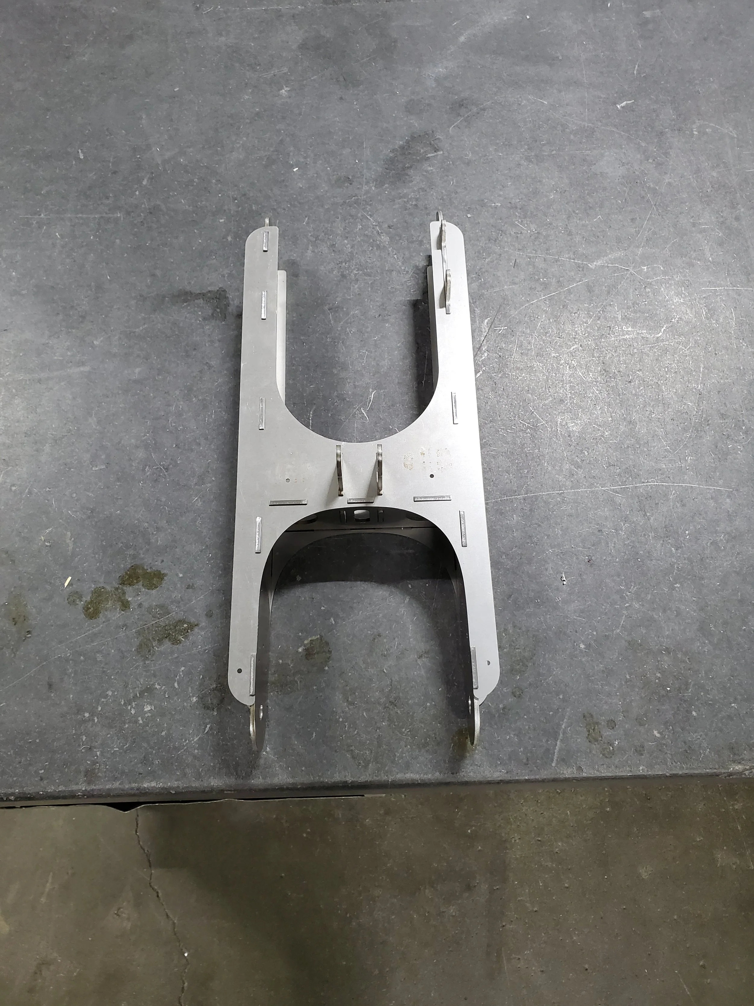
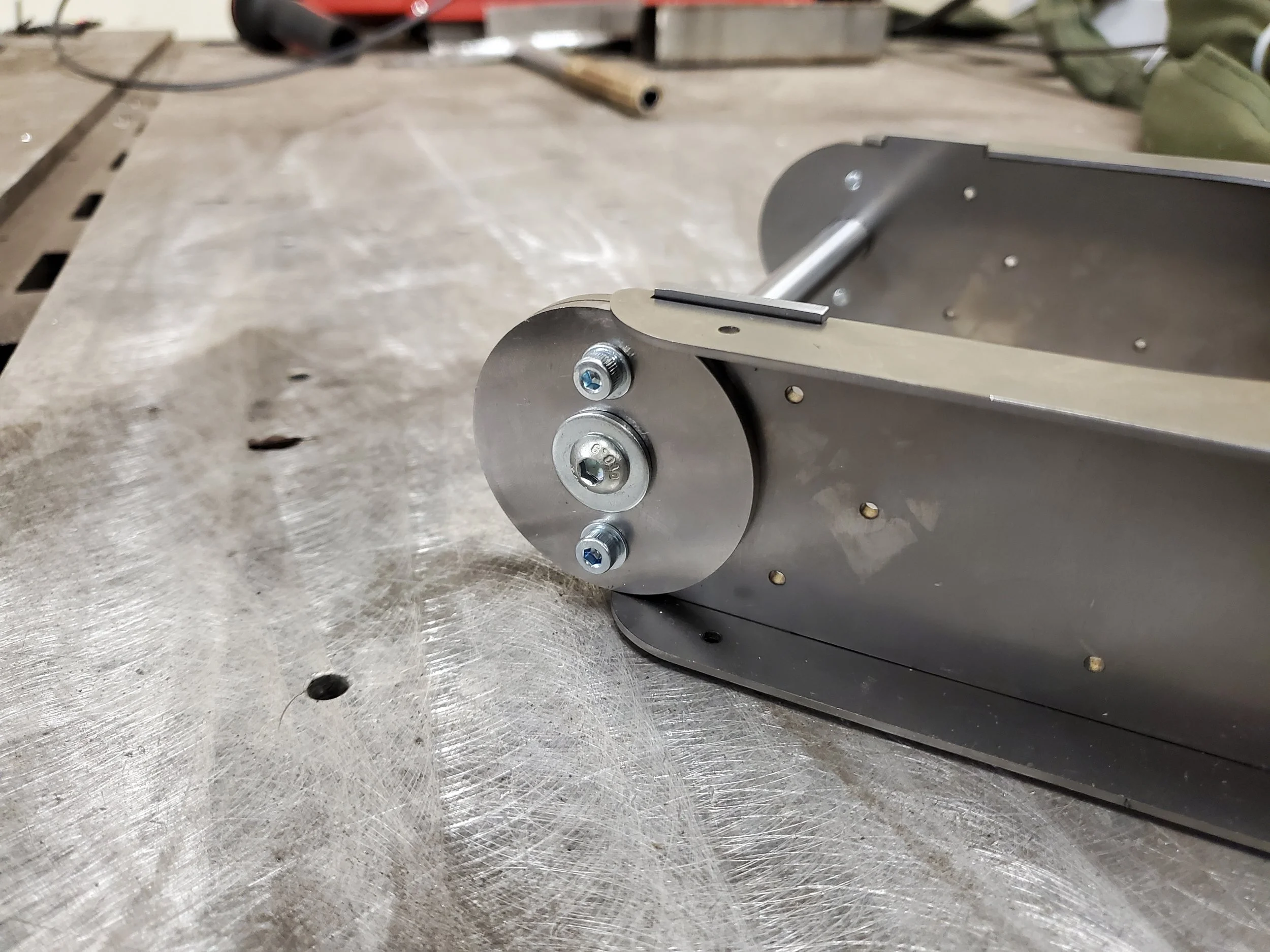
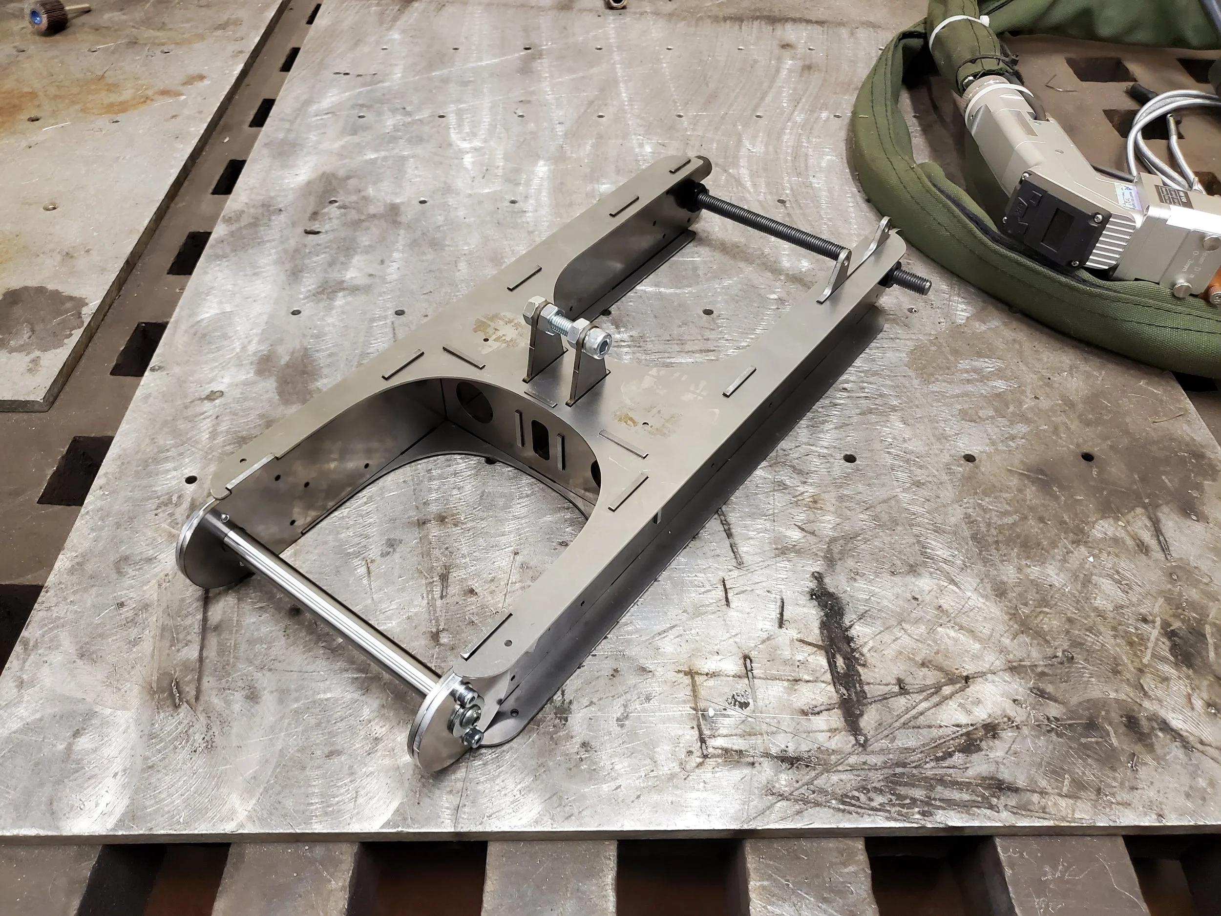
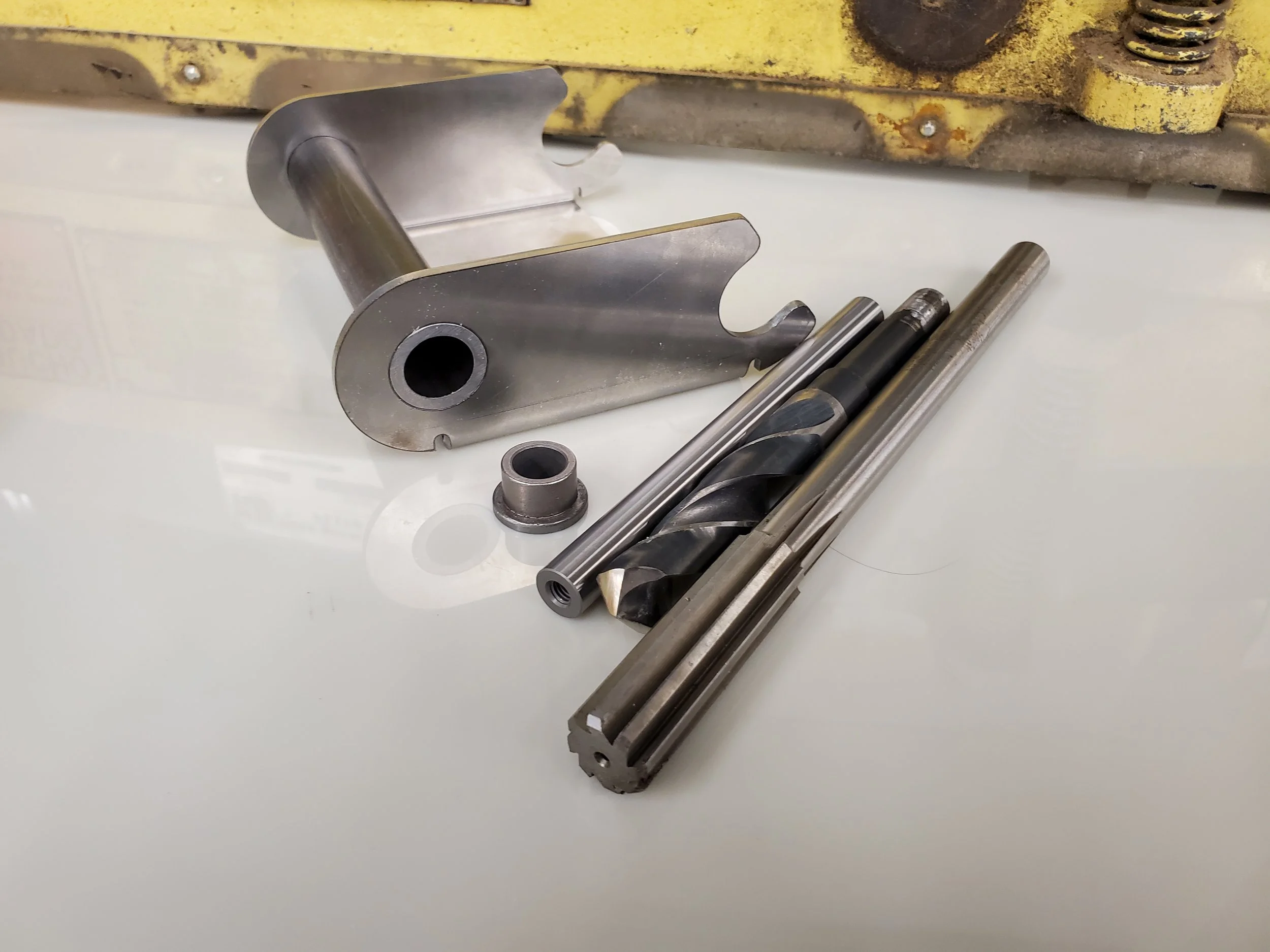
The swing arm was designed as a slot-and-tab welded design as highly-accurate, laser cut components are very easy to design and acquire from online services. Additionally, jigging things together should be simple as everything is self locating.
The pivot point will use simple bearings as the rotational relation is relatively low speed, low angle.
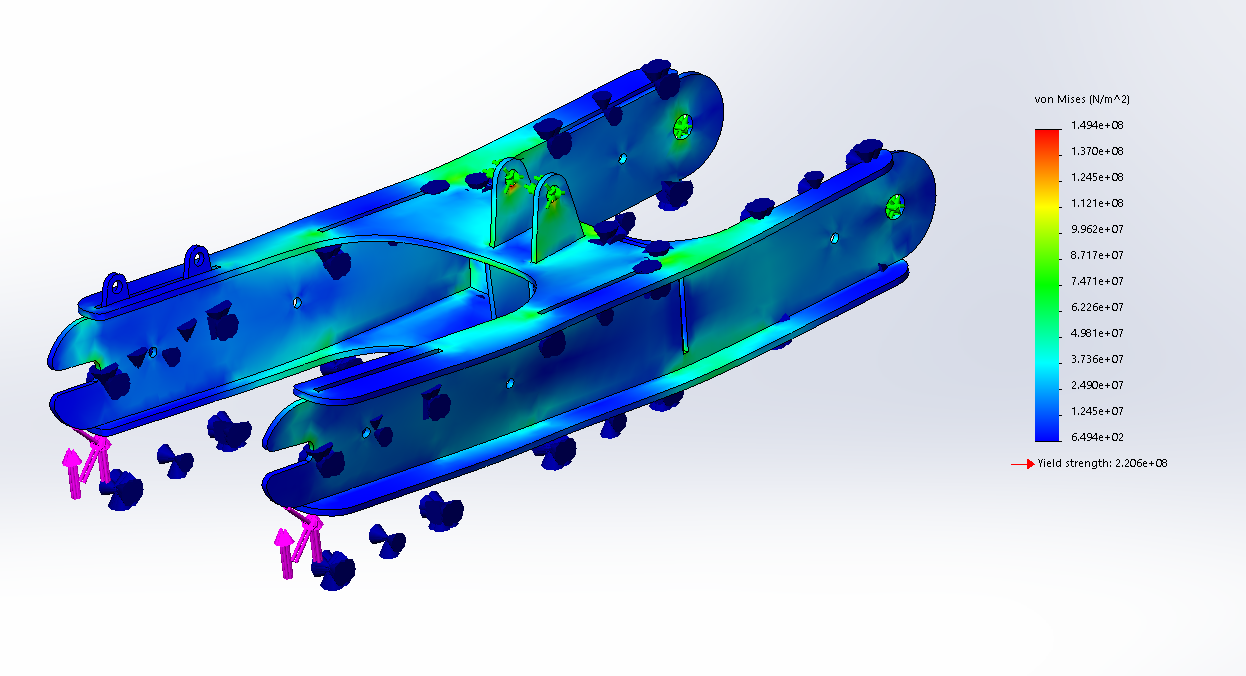
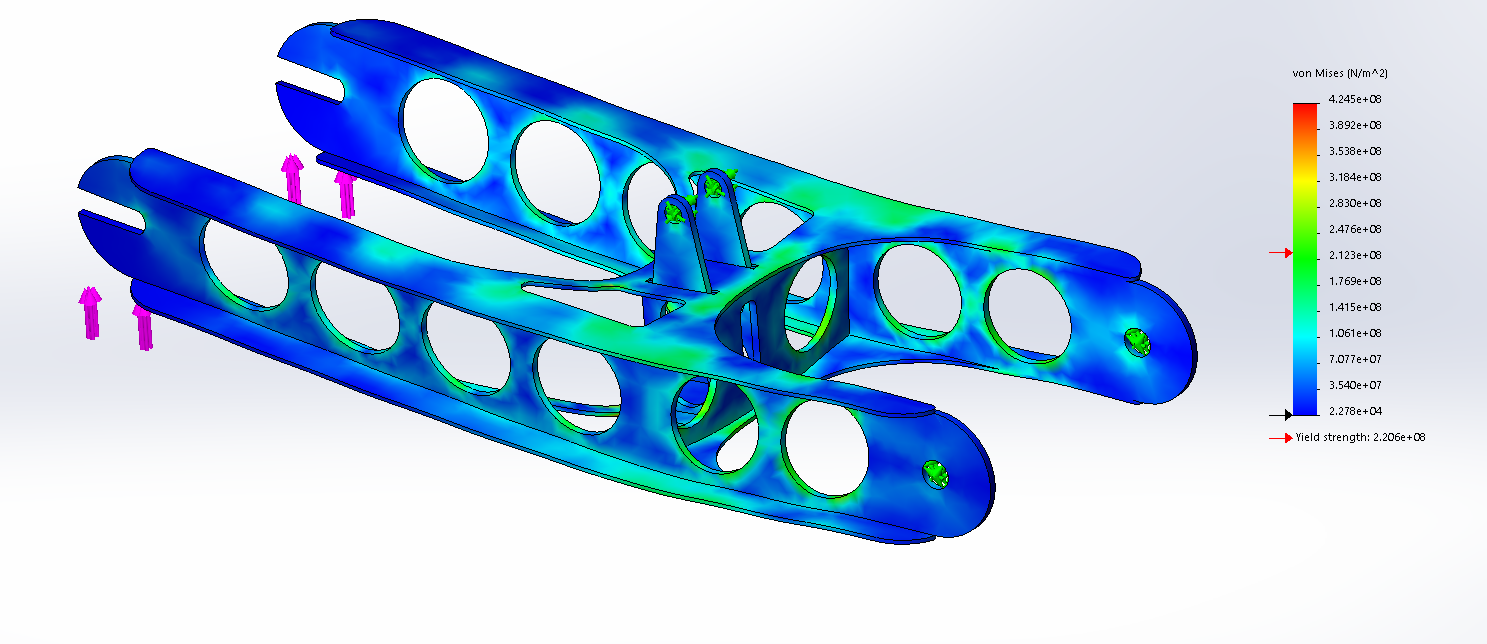
Because this component undergoes so many forces, I performed some structural analysis to make sure I wasn’t going to lose any skin if it falls apart. The loading conditions were mild to extreme scenarios.
Some attempts at weight reduction were taken but were ultimately scrapped as the the weight reduction relative to the overall assembly was not worth the potential for failures.

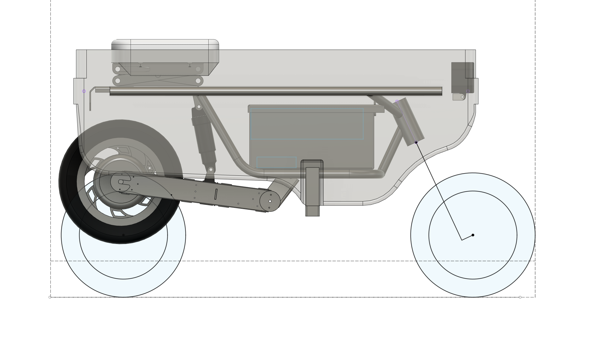
To be continued…
The swingarm will be attached soon. Key components remaining are a battery/controller enclosure, collapsible seat mechanism, and bracketry for mounting lights, foot pegs, and other accessories.